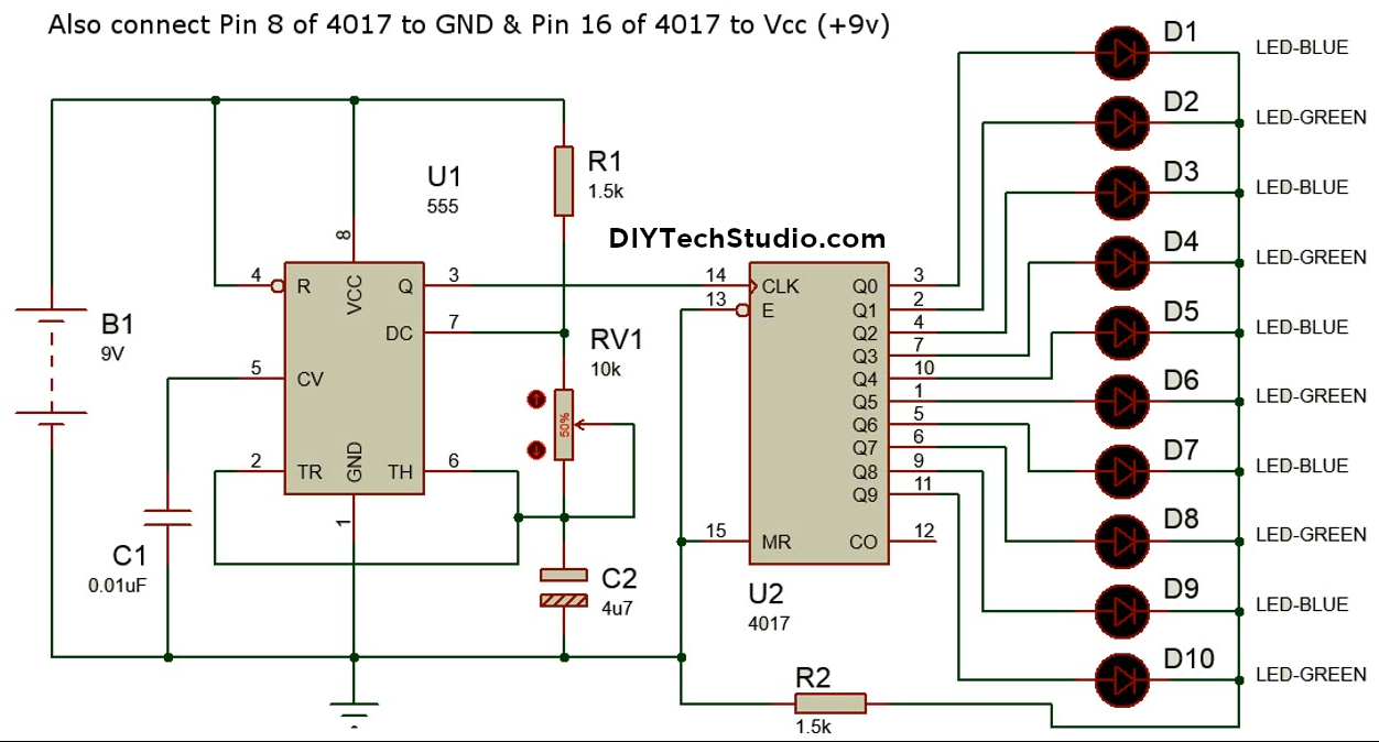
Led chaser circuit diagram pdf Charger light circuit diagram Led chaser 4017 circuit
Dancing LEDs pcb diagram - Schematic Power Amplifier and Layout - How
4017 led chaser Frequency divider circuit using 555 and 4017 in 2020 (met afbeeldingen) Dice 4017 diagram circuits example datasheet
4017 and 555 circuit diagram
Heart shaped serial led flasher circuit diagram using ic 555 and ic 4017Led chaser using 4017 counter and 555 timer Led roulette circuit diagram using 555 timer ic & 4017 counterTimer 4017 555 counter circuit begingroup.
555 4017 counter timer using schematic led circuit problem circuitlab created electricalSequential led circuit diagram Circuit 4017 555 roulette led timer ic diagram usingLed chaser using a cmos 4017 and a 555.

Led chaser circuit using 4017 555 diagram cmos light seekic ic
4017 led chaser 555 pcb using timer bottom counter icAstable circuits functional block diagram figure timer within lines double multivibrator Circuits using 555 timerCircuit diagram 4017.
Digital dice circuit diagram using ic 555 & ic 4017Using a 4016 to control a 555? 555 timer astable multivibrator circuit diagramChaser led needed components.

Led chaser circuit using ic 4017 and 555
Led roulette circuit using 555 timer & 4017 ic4017 circuit diagram Switch circuit 4017 off ic diagram toggle latching push press using circuits4017 led flasher 555 pattern circuit circuits counter decade timer projects gr next pulses.
Control using thanksPin on projects 4017 ic diagram circuit led timer heart roulette serial flasher shaped description using circuitdigest circuits choose boardRunning light 555 + 4017 dip kit.

Led chaser 4017 circuit 555 diagram sequencer simple timer using circuits light cd4017 projects ne555 counter leds blaster make step
4017 ic project circuit diagram4017 555 timer climbing decoded outputs astable 4017 led ne555 chaser sequencer circuit using cd circuits diagram flasher 555 ic projects electronic volt popular blinker electronics gr555 ic timer circuit diagram astable using pinout pins multivibrator block description ic555 monostable internal circuits ground board explain power.
4017 counter circuit internal decade digitalOn off latching switch circuit diagram using ic 4017,555 Circuit designDice circuit digital ic diagram 555 using 4017 electronic led circuits clock.

Circuit traffic dancing diagram pcb leds 4017 555 light project schematic using projects led moving flashing electronic layout electrical signals
4017 led chaser 555 circuit ic using sine wave circuits oscillator cd4017 running datasheet lights pcb frequency low eleccircuit pinoutLed chaser circuit with pcb layout 4017 led chaser circuit diagram with rgb ledMusic box circuit using a cd4017 and two 555.
Dancing leds pcb diagramCircuit chaser led 4017 555 ic using counter diagram timer circuits light decade leds running flasher sequential 555 counter circuit4017 decade counter circuit diagram.

Frequency divider circuit electronicshub
Led 4017 chaser easyelectronicsprojectRoulette 4017 555 timer counter ic decade electricaltechnology ‘555’ astable circuitsLed sequencer / chaser using ne555 & cd 4017.
.


4017 And 555 Circuit Diagram

4017 Decade Counter Circuit Diagram

Charger Light Circuit Diagram

4017 Counter

4017 LED Chaser - TechSaw 4017 LED Chaser

circuit design - 555 timer with 4017 counter - Electrical Engineering